eBook Automating Manufacturing Systems; with PLCs
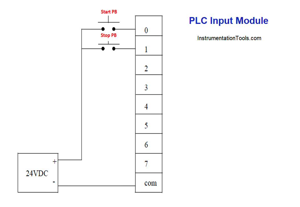
PLC Input Module Block Diagram PLC Input Module Circuit Diagram. It is clear form the above figure that the input module is consist of two section one is power section while the other is logical section, which are electrically isolated from each other. When push button is closed 220V AC is applied to the bridge rectifier, through resisters R1.

PLC Inputs What They Are, Different Types And Much More Engineer Fix
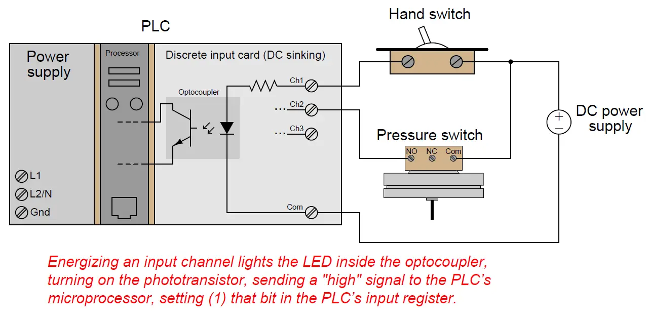
Discrete Input Modules A "discrete" data point is one with only two states on and off. Process switches, pushbutton switches, limit switches, and proximity switches are all examples of discrete sensing devices. In order for a PLC to be aware of a discrete sensor's state, it must receive a signal from the sensor through a discrete input channel.
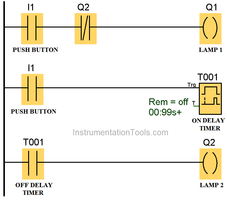
PLC Automatic Control of Two Outputs with one Input PLC Examples
In this video, we learn about PLC input and output modules in the programmable logic controller. Hardware Parts and components in PLC.Get PLC tutorials here:.

Basics of PLC Programming PLC Tutorials for Beginners What is PLC
1. 24V Digital Input Module for PLCs and IEC 61131-2. In a PLC, the Digital Input Module is used to receive external 24V digital inputs from sensors or switches and transmit signals to the host controller. Fig. 1 shows the basic configuration of the 24V Digital Input Module.
Principle of Operation of PLC Inst Tools
PLC controller output. the most commonly used devices are motors, solenoids, relays, indicators, sound signaling and the like. When starting a motor or a relay, the PLC can manage or control a simple system such as the system to classify products into complex systems such as the service system to position the head of the CNC machine.

PLC Hardware Components (Explained in Plain English) PLC Academy
Contents What is a PLC? PLC stands for "Programmable Logic Controller". A PLC is a computer specially designed to operate reliably under harsh industrial environments - such as extreme temperatures and wet, dry, and/or dusty conditions.

Electronics Blog PLC Input Circuit for PSoC, Raspberry Pi, Beagle, OLinuXino, Cubieboard High
Optocoupler Input Circuits for PLCs by Lewis Loflin Here I'll introduce programmable logic controller (PLC) input circuits using opto-couplers. We use these devices to interface high voltage sensors to low voltage microcontroller logic and to isolate sensitive circuits from noise. I'll also discuss the concepts of SOURCE and SINK.
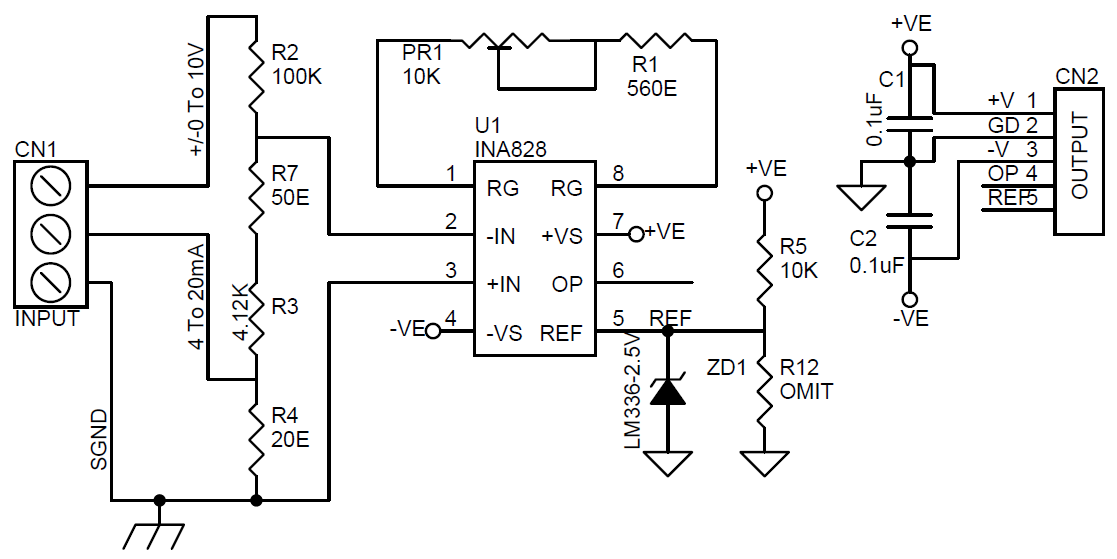
420mA / ±10V Analog Input Module for PLC
In a PLC system there will usually be dedicated modules for inputs and dedicated modules for outputs. An input module detects the status of input signals such as push-buttons, switches, temperature sensors, etc.. An output module controls devices such as relays, motor starters, lights, etc. Discrete I/O
One Function of a Plc Input Interface Module Is to GracehasWiggins
This opto-coupled arrangement makes each input channel of a PLC rather rugged, capable of isolating the sensitive computer circuitry of the PLC from transient voltage "spikes" and other electrical phenomena capable of causing damage:

Plc inputs and outputs explained in detail The Automization
Common PLC Input Devices In most PLC applications, there are a number of components that you will usually see. To name a few, there are push buttons, selector switch, and limit switches. Push buttons PLC Basics: Push buttons (Photo from Siemens) Push buttons are the ones that you will usually see as START or STOP buttons in a PLC control system.

All About PLC Analog Input and Output Programming
Get deals on plc inputs in Industrial products on Amazon. Browse & Discover Thousands of products. Read Customer Reviews and Find Best Sellers

Making Multi Way Switches using PLC Switch Control PLC Logic
The Corona design provides the front-end interface circuit of a PLC digital input module. The design accepts high-voltage inputs (36V, max) and features isolated power and data, all integrated into a small 90mm x 20mm form factor.

Plc Input Circuit Diagram Circuit Diagram
by Doug Taylor on July 23, 2020 Why are there so many types of PLC inputs and outputs? Modern PLCs are adaptable devices. Since ladder logic can work with analog values as well as on-off devices (called discrete inputs and discrete outputs), PLCs have evolved from their relay rack roots into very configurable systems.

Plc Input Wiring Diagram
What is the Input and Output Module in PLC? Multiple inputs (I) and output (O) modules are used in the PLC system. They provide an interface between the central processing unit (CPU) and programmable devices. What is Input Module? The module which interacts with the input signal is called as Input Module.

PLC Digital Input and Output Modules Instrumentation Tools
A DI is a circuit designed to receive a binary signal transmitted from an industrial sensor and translate that input into a reliable logic signal for a PLC or industrial controller. Common examples of industrial binary signals are pushbuttons and/or temperature or proximity threshold indicators.
PLC Wiring Diagrams PLC Digital Signals Wiring Techniques
Digital Input Modules Digital Input (DI) modules are used in Programmable Logic Controllers (PLCs) and Motor Drives to receive 24-V digital inputs from field sensors and switches. Isolation is used to manage ground potential differences. The input signal is interpreted as a logic high or low using a voltage comparator with hysteresis.